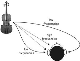
Figure 1 - Directional hearing cues
To buy the book from which this article came (as a paper or as a Kindle book) go here.
Many music traditions betray an interest in the positioning of instruments and vocalists relative to one another; especially so when music is combined with drama. It is therefore appealing to construct electronic recording and reproduction systems which can capture and recreate these antiphonal, spatial effects. More fundamentally, music takes place in spaces, and the acoustic of those spaces is often a vital component of the overall effect. A mass setting by William Byrd would not sound "right" without the long acoustic reverberation of a large church or cathedral. A spatial audio system aims, not only to capture and recreate the positional information of the musicians themselves, but to place them in a convincing acoustic. Synthetic music too aims to create, not only music, but a synthetic environment in which it is "performed".
Consider the situation shown above, in which an experimental subject is presented with a source of sound located at some distance from the side of the head. The two most important cues the brain uses to determine the direction of a sound are due to the physical nature of sound and its propagation through the atmosphere and around solid objects. We can make two reliable observations:
It may be demonstrated that both effects aid the nervous system in its judgement as to the location of a sound source: At high frequencies, the head casts an effective acoustic "shadow" which acts like a low-pass filter and attenuates high frequencies arriving at the far ear, thus enabling the nervous system to make use of interaural intensity differences to determine direction. At low frequencies, sound diffracts and bends around the head to reach the far ear virtually unimpeded. So, in the absence of intensity-type directional cues, the nervous system compares the relative delay of the signals at each ear. This effect is termed interaural delay difference. In the case of steady-state sounds or pure-tones, the low-frequency delay manifests itself as a phase-difference between the signals arriving at either ear. The idea that sound localisation is based upon interaural time differences at low frequencies and interaural intensity differences at high frequencies has been called Duplex theory and it originates with Lord Rayleigh at the turn of the twentieth century.
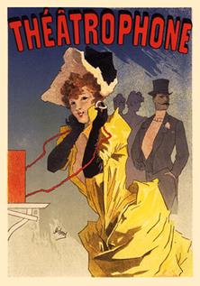
The simplest, and in some ways the best, stereo system was invented in 1881, when Monsieur Clement Ader placed two microphones about eight inches apart (the average distance between the ears) on stage at the Paris Opera where a concert was being performed. He relayed these signals over telephone lines to two telephone ear pieces at the Paris Exhibition of Electricity. The amazed listeners were able to hear, by holding one ear piece to each ear, a remarkably lifelike impression that they too were sat in the Opera audience. This was the first public demonstration of binaural stereophony, the word binaural being derived from the Latin for two ears.
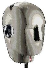
The techniques of binaural stereophony, little different from this original, have been exploited many times in the century since the first demonstration. However, psycho-physicists and audiologists have gradually realised that considerable improvements can be made to the simple spaced microphone system by encapsulating the two microphones in a synthetic head and torso. The illusion is strengthened still more if the artificial "dummy" head is provided with artificial auricles (external ears or pinnae). The binaural stereophonic illusion is improved by the addition of an artificial head and torso and external ears because it is now known that sound interacts with these structures before entering the ear canal. If, in a recording, microphones can be arranged to interact with similar features, the illusion is greatly improved in terms of realism and accuracy when the signals are relayed over headphones. This is because headphones sit right over the ears and thus do not interact with the listener's anatomy on the final playback.
Binaural audio is theoretically capable of recreating perfect, accurate sound-fields; apparently reproducing sounds from all directions at the ears of the listener and the system only requires two discrete recoding channels, so it is therefore efficient in engineering terms too. However, some important limitations should be noted. Firstly, by making mouldings of experimental subject's pinnae, experiments have consistently shown that subjects are far better at judging the direction of sounds when utilising their castings of their own pinnae than when listening with another person's external ear mouldings. It seems that during childhood experience we learn to listen with our "own ears". This would not be such a depressing limitation were it not for the fact that every person's pinnae are as unique as their finger prints. Secondly, and most damning of all, there appears to be a very real commercial drawback imposed by the system's method of signal presentation over headphones. Music listening is both a shared activity and a process which is shared with other activities, and headphones prevent both.
The desire to re-create spatial sound-fields without headphones has been recognised since the very earliest experiments with stereophony. However, if the signals from a dummy head recording are replayed over two loudspeakers placed in the conventional stereophonic listening arrangement (with loudspeakers arranged at ±30° to the centre), the results are very disappointing. The reason for this is the two unwanted crosstalk signals: the signal emanating from the right loudspeaker which reaches the left ear; and the signal emanating from the left loudspeaker which reaches the right ear. These signals result in a failure to reproduce the correct interaural time delay cues at low frequencies. Several researchers have proposed and constructed systems in which complementary cancelling signals were fed to the speakers to cancel these crosstalk signals (Roland RSS System & Thorn EMI Sensaura). Unfortunately, to work well, the system required that the listener held one, very precise position, a situation which invalidated the convenience and companionship of loudspeaker listening.
Two loudspeaker stereophony has restricted ambitions compared with binaural stereo. When listening to music on a two-channel loudspeaker stereo audio system, a sound image is spread out in the space between the two loudspeakers. The reproduced image thus has some characteristics in common with the way the same music is heard in real-life - that is, with individual instruments or voices (known as phantom images) each occupying, to a greater or lesser extent, a particular and distinct position in space. However, insofar as this process is concerned with creating and re-creating a sound-event, it is limited in that the image occupies only the space bounded by the loudspeakers. Nevertheless, the system has proved popular and endured for fifty years as the staple presentation of audio. Only in the last twenty or so years have multi-channel systems become a reality, which aim to produce artificial sound-fields which surround or "immerse" the listener.
Two different techniques are used in the production of most stereo recordings. The first is a system that was invented in 1928 by Alan Blumlein - a British genius working for EMI (see box p. 614). This is by far the most commonly employed system and is based on encoding phantom image positions by means of inter-channel amplitude differences. The second system is much rarer, and is based on encoding inter-channel time differences between the stereo channels. Both systems are described below.
Blumlein was well aware of Duplex spatial-hearing theory and gives a good pr�cis in his patent application (1932). He therefore expected that the high-frequency inter-aural intensity cues and low-frequency inter-aural delay cues would be formed differently.
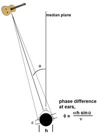
Figure 4 illustrates a real, sound source auditioned in real life. Considering the low-frequency case, the two ears of the listener are spaced distance h apart. The sound source is placed so that its direction is θ° to the straight-ahead position. The sound will travel further to the right ear than to the left. If v is the velocity of sound in air, the time interval between the arrivals of the sound at the two ears will be,
( h sin θ ) / v
Because h is small compared with the distance from the source there will be a phase difference,
Φ = (ω h sin θ ) / v
where ω is 2π times the frequency of the sound wave.
If a recording and reproduction system can be designed which exactly recreates, by means of the correct sound pressures at the ears of the listener, the original time differences of arrival, the listener will experience a virtual sound source at angle θ.
Φ δ
= [(L - R) / (L + R)] . [(ω h sin ψ) / v ]
................................ (A)
Thereby demonstrating that any given phase shift
may be derived at the listener's ears by means of the appropriate ratio of
in-phase signals (L and R) fed to the loudspeakers set at 2ψ° apart.
[1] This
equation is central to understanding how stereo systems operate. Figure 6
illustrates this diagrammatically.
But how might the sound signals be encoded or captured
to create the appropriate inter-channel amplitude ratio? One answer is to
"steer" sound sources into a particular position using a ratiometric
potentiometer designed progressively to attenuate one channel whilst
progressively strengthening the other as the knob is rotated; the input being
shared equally between both channels when the knob is in its centre (12
o'clock) position. Such a control is referred to as a panoramic
potentiometer or pan-pot for short.
This technique is the norm for the huge majority of stereo
recordings both today and for the last 50 years! In this procedure, each
instrumentalist or vocalist is close-miked and the result of the mix of all the
instruments combined together electrically inside the audio mixer; the apparent
position of each instrumentalist within the stereo picture being set via the
setting of the pan-pot. Note that all pan-pots encode stereo information by inter-channel
intensity differences alone; they can therefore be regarded as a version of
Blumlein's intensity-derived stereo system.
For the capturing of real sound-fields something more
subtle is required. Clark et al. (1958) describing the commercialisation
of Blumlein's EMI stereo system [2]
thirty years after Blumlein's original patent was written, show how the
sound-field may be sampled so as to recreate the appropriate phase-shifts at
the listener's ears. Clark and his team opted for a coincident stereo
microphone technique based on crossed figure-of-eight (velocity) microphones.
Given that the output of a velocity microphone follows
a cosine law as shown in Figure 7, the microphone voltages derived from a horizontal
crossed pair, placed together, angled 90 degrees apart and inclined so that
each pair is placed such that its maximum response is at 45 degrees to the
median plane, will be,
EL =
k. sin ( 45o + θt )
ER = k. sin ( 45o - θt )
where θt is the true
angle of the recorded sound source from the median plane.
From which it may be derived that,
( EL - ER ) / ( EL +
ER ) = tan
θt ............................ (B)
sin θa
= tan θt . sin ψ ............................................
(C)
where θa is the apparent
angle of reproduced sound.
We can plot (as Clark et al. did) θt
against θa for various values of ψ.
This graph is reproduced as Figure 8. The curves represent the perceived angle
(y axis) versus the captured angle (x-axis) for an
encode-decode system with the signals captured from perpendicular, crossed
figure-of-eights replayed over loudspeakers the base angles of which subtend either
60° at the listening position (ψ = 30°), or 90° at the
listening position (ψ = 45°).
As you can see, when the loudspeakers are disposed at
30° either side of the listener, as in the classic stereo layout, the captured
sound-stage is cramped so that the original, captured 90° is compressed to the
reproduced 60°. However, the scaling is fairly linear. Interestingly, the case
for � 45� loudspeakers is plotted too in the figure. This illustrates that a 90
degree soundstage may be accurately produced by such a system. In fact,
equation C illustrates that a perfect illusion of the original
sound-event may be created by the EMI system; at least at frequencies below
700Hz[3].
Unfortunately neither Blumlein himself, nor the
post-war team of Clark, Dutton and Vanderlyn, were able to offer such thorough theoretical
analysis for HF imaging. It was clear to them that amplitude differences
alone, caused by the shadowing effect of the head, and must account for the
perception of direction at high-frequencies[4].
But, in the computer-less world of 1928, a thorough geometrical analysis of the
baffling effect of the head and upper torso would have been a gargantuan task.
Their approach as practical engineers was therefore empirical. The question
they sought to clarify and answer was: Now that we know what amplitude ratios
are required to generate the correct phase-difference cues at LF for the
listener, what ratios are required at high-frequencies? As Clark et al. say in
their 1958 paper[5],
As the quotation clearly illustrates, the experiments by
Clark et al. led them to discover two points:
Really, this should not come as any great surprise; it
would be fortuitous indeed if two entirely different perceptual mechanisms
could reveal perfectly similar illusions for the same inter-channel amplitude-ratio.
The net result of these
findings is that, on a real, wideband music signal the stereo image is
"smeared" with the high and low frequencies failing to "map" on top
of one another. Figure 11 (left) illustrates this well, where it may be seen
that the frequency range around 10kHz produces a much "steeper" curve compared
with the curve for low and mid-frequencies.
As the EMI REDD team put it in the manual for their Stereosonic
mixing consoles (REDD 1959),
The image in Figure 9 is an attempt to give
a visual analogy for this effect. Interestingly, the acoustic effect is
analogous to chromatic aberration in a lens, in which the high frequency blue
light is refracted differently to the low-frequency red light.
They accomplished this signal manipulation by deriving
a sum signal (L + R) and difference signal (L - R) and inserting a low-pass
filter into the difference channel. They invented a matrix and filter circuit
to accomplish this and they referred to this technique as Stereo Shuffling.
Below is an illustration of their practical circuit and its implementation in
the difference channel.
Unfortunately, the EMI Shuffler circuit, party
due to a lack of comprehension, and partly due to a sub-optimal implementation,
was either omitted or abandoned as part of the standard stereo system and a
belief gradually engendered that congruent low-frequency and high-frequency
stereo images may be created by simple ratiometric inter-channel ratios. Even
the best of all the expensive and exotic mixers of today and yesteryear ignore the
findings of EMI and others, so that today (and for sixty years) stereophonic
sound has never delivered on the promise its inventor had for it nearly a
century ago! Rather compromise and "good enough" have ruled the day. The loss
of the EMI Shuffler technique left the stereo system broken - a situation which
has effectively lasted until today.
Psychological experiments demonstrate that there
exists another method of steering a phantom image into positions along the axis
of two loudspeakers by inter-channel delay differences rather than intensity
differences. Clearly a central phantom image may be derived in which both
channels receive identical signals, identically timed. In fact, the situation
is indistinguishable from that produced in intensity-derived localisation.
Experiments using a variety of sounds demonstrate that, when the inter-channel
delay is approximately equal to 1mS, the sound localises at the speaker
receiving the earlier of the two signals. The postulated mechanism for this observed
phenomenon is an inhibition system in the auditory processing which suppresses
directional cues arriving approximately 1mS after the first set of interaural
cues. Alternatively termed the law of the first wave front or the precedence
effect, it is believed that the auditory system, having been developed over
millions of years in the presence of reverberation, prioritises the first set
of auditory cues it receives, which it takes to be the direct sound, from later
signals, which it assumes are reverberation effects. In between, the two
extremes of 0mS delay (where the image is central) and 1mS delay (where the
image localises at the loudspeaker producing the earlier signal) a progressive,
but confused relationship emerges. Between these two boundary conditions, the
auditory system appears partially to fuse the staggered signals and tries to
derive reliable directional information. The orthodox conjecture is that inter-channel
delay derived stereophony presented via loudspeakers works because of some kind
of gradual onset of the precedence effect.
However, delay-derived stereophony isn't a reliable
system, and a moment's thought will demonstrate why. If we imagine a wideband
sound (composed of many simultaneous sine waves) panned away from the centre by
introducing a delay D, those frequency-components with wavelengths
which are similar to D . Ss (where Ss
is the velocity of sound in air), will recentralise, because the phase
difference between them will return to zero. Figure 11 (right hand graph) illustrates
the results of a study by Wendt (Blauert 1983) and shows the position of
phantom-images derived by inter-channel delay difference. As the graph shows,
perceived position depends heavily on the frequency component of the experimental
stimulus[6].
Note that the studies with signals with a wavelength similar to (D . Ss)
do show exactly the type of predicted recentralising effects.
Because inter-channel intensity derived stereo
is greatly the superior system (a comparison of Figure 11 left and right graphs
demonstrate this admirably), the vast majority of stereo material is produced
using inter-channel intensity coding. In short, most records are multi-tracked
and electrically panned. Nevertheless, an important application of
delay-derived stereo exists in classical music recording with the use of spaced
pressure-sensitive (omnidirectional) microphones. This system, and its "cousin",
the Decca Tree, create a stereo illusion due to time-of-arrival information
collected at spaced microphones. If we look at the practical arrangements, we
can see that they are calibrated to give results similar to those illustrated
in Fig. 11 (right), from which we deduce that we need at least 1mS delay
to give a full-left/ full right impression. With a one metre spacing, and a
maximum obliquity of 30 degrees from the centre (which implies the spaced pair
is being deployed very close to the performers), the maximum inter-channel
delay is given by,
sin 30° .
1/ Ss in mS
where Ss is the speed of
sound in air expressed in metres/second.
The result is 1.47mS for the maximum inter-channel
delay for an Ss taken as the nominal 340 metres/second. This also
explains why the infamous 3:1 rule exists for the layout of omni microphones because, if the
microphones are some distance from the performers, the obliquity is limited and
therefore there is a commensurate requirement to space the microphones further
apart to get the adequate inter-channel delay.
Many beautiful recordings have been made using the
spaced-omni and Decca-Tree approach. However, it is only fair to point out that
no successful theoretical underpinning has ever been derived for such
recordings as the time-of-arrival data is scrambled on replay over
loudspeakers. This is illustrated diagrammatically in Figure 12.
Once again, we invoke the precedence effect to explain
this, so that the later signals (shown bracketed) are suppressed in favour of
the earlier. As recording is as much an artistic enterprise as it is an
engineering discipline, this lack of engineering rigour is justifiable.
There exists a parallel literature in the history of spatial
sound reproduction which aims to recreate the original sound-field at the
listening position. These techniques are termed wave field synthesis
(WFS). This latter approach runs something like this. The ideal mono
reproduction system provides a window from the listening space (typically a
small room) into the performance room (a much larger space - like a concert
hall). This is illustrated in Fig. 13.
Extending this argument, stereo appears to provide for
two windows into the performance space and multi-channel audio systems (like
5.1, considered in next chapter) are an extension to provide multiple windows;
as shown in the diagram. It follows that there must be a point at which enough
wall has been replaced by windows that the listener's experience will match
that of being in the hall itself, rather than in the listening space. If enough
microphones sample the sound-field, and enough loudspeakers are used to
recreate it, the listener will experience the sound waves as they were in the
original hall. She will therefore be able to turn her head and move around
within the space and experience the sound just as she would have been able to
do at the original concert. The aim is therefore to recreate the amplitude and
the phase of the sound waves as they would have originally been. The analogy is
often drawn with holography and an alternative term for wave field synthesis is
holographic stereophony. Wave field synthesis relies on Huygens'
Principle which states that,
Each
point on a primary wave-front can be considered to be a new source of a
secondary spherical wave and that a secondary wave-front can be constructed as
the envelope of these secondary waves.
Figure 14 illustrates Huygens' principle. In our case,
each electro-acoustic channel (microphone-loudspeaker) is one of Huygens'
secondary sources as shown in Figure 15.
The problem with this argument is that, without an
enormous number of channels and loudspeakers, a WFS system can never provide a
faithful spatial reconstruction of a sound-field. Sometimes it is assumed that the
wave-front reconstruction approach underpins spaced microphone techniques. This
is quite wrong and the reason is illustrated in Fig. 12. In the upper part of
the diagram, the sound emanating from an instrument is detected by a pair of
ears in the original performance space. In the lower part of the diagram, the
acoustic signals experienced via two windows are illustrated.
If we imagine a sound like a sharp, single shot on a
drum (nearly an impulse response), we can derive the sounds which will arrive
at the two ears in each case. These are illustrated too. It is immediately
obvious that the signals arriving at the ears are completely different
in each situation. In fact, the only reason the "two-windows" system works
is due to the law of the first wave-front suppressing the later cues. Systematic,
mathematical analysis, in which the integral of the results from the secondary
wave-fronts are computed and compared with the original wave-front, shows that
the only way that holographic stereo can be made to work is to construct a
system in which the approaching sound wave-front is sampled at many, many points
- as if through a very wide window (Figure 16). Electrically this could be achieved
with a "curtain" of microphones producing signals carried in separate channels
and produced by separate "curtain" of loudspeakers. Theoretical analysis
demonstrates that the spatial sampling (the number of transducers per unit
length) must be less than 1 wavelength at the highest reproduced frequency
for non-aliased spatial images: in other words, a microphone and
loudspeaker every 2 cm! There are also problems with the finite length of the
loudspeaker array which cause, so called, truncation artefacts which are
analogous to the hard edge of the listening window and to the requirement for
windowing in the time-frequency Fourier transform.
The phenomenon of the law of the first wave-front imposes
limitations on intensity-derived stereophony. The preference that our auditory
system has for initial auditory cues over subsequent cues causes the illusion
of intensity derived stereo to collapse when the listener moves from the
listening position at the apex of an equilateral triangle between the
loudspeakers (see Figure 5). The construction of a stereo image is said to rely
on the listener occupying a small sweet spot where the image is reliably
experienced, this limitation is due to the law of the first wave-front.
Apart from the fact that the majority of records are
mixed for domestic surroundings, the purist two-loudspeaker, summing
stereophony proposed and engineered by the EMI team fairs badly when reproduction
is required in a large auditorium. Inevitably, in a large space, many people
will not be located at the ideal listening position or sweet spot. Analysis
demonstrates that a listener sat far away from the sweet-spot will experience
incorrect - or even paradoxical - phase differences at the ears of the listener
so that the image (at certain frequencies) will even appear outside the
baseline of the loudspeakers.
On the other side of the Atlantic, in America, the demand for stereo sound came predominantly from the cinema industry. Their
starting point was therefore entirely different. Steinberg and Snow's work at
Bell Telephone Laboratories (1934) in the early nineteen-thirties was the first
serious and systematic investigation into spatial audio in America (their term was Auditory Perspective). Their investigations started with the
premise that they wanted to re-create in a large auditorium the spatial
positions of actors on a sound-stage. Their equipment was disposed as shown in
Figure 17. Their methodology was empirical and was based on an experiment in
which a group of listeners in an auditorium with various numbers of loudspeakers
marked the perceived positions of a caller in a separate room, in which various
numbers of microphones were installed.
The real position of the caller is marked on the left
hand side. The results for a three microphone - three loudspeaker arrangement
are shown in the diagram (top). There is some distortion of the depth of the
illusion - especially in the centre. Nevertheless the results were deemed
acceptable. They then tried a two-channel arrangement and their results are
shown in the diagram too. The major distortion here exists in the centre of the
soundstage; which is probably the worst place for the image to be distorted.
They tried further hybrids of three microphones to two loudspeakers and two
microphones to three loudspeakers, in search of a more economic arrangement
(remember microphones, amplifiers and loudspeakers were expensive in 1930).
None was found, and they concluded that the three-channels was the minimum
number to affect a reasonable illusion of width and depth. This work formed the
foundation of multi-channel, cinema audio systems which we shall meet next
chapter.
We have arrived at a point in which we can survey past
and present stereo sound systems and, unfortunately, the summary is rather a
dispiriting one. We have binaural techniques, capable of remarkable realism and
engineering parsimony, but which have failed consistently to attract consumer
interest or acceptance. We have conventional, two-channel, inter-channel
intensity derived stereophony: the most successful, and certainly the hardiest
of the systems, but broken within years of its invention and never mended. We
have wave field synthesis which has yet to leave the laboratory: and various
spaced microphone systems which were either originally conceived for cinema, or
labour under a fallacious theoretical model.
All in all, not a pretty picture! So, it is with this
depressing litany in mind that the rest of the chapter is devoted to
re-visiting Blumlein's stereophony and how it might be improved because,
despite its rather drab lack of modernity, intensity-derived stereo remains the
format which works in cars, on personal stereos and on hi-fi systems of all
types. It has outlived its many challengers - from Quadrophony to 3D-sound, and
survived into the digital, on-line age as the format of the vast majority of
MPEG files. It is also the format in which the vast majority of the rich back-catalogue
of music is preserved. So any benefits which might be teased from this old
technology may have benefits for past, as well as for future, recordings.
You will remember that channel-intensity panned stereo
recordings (and stereo recordings made with coincident microphones) are all
"broken" without modification of the channel intensities with respect to
frequency. A visual analogy of the effect was illustrated in Figure 9 which
shows how, as the sound image gets further from the centre, it is split into
non-coincident high-frequency and low-frequency components. The EMI team who
developed the modern, intensity-derived stereo system tackled this problem by
inserting a low-pass filter in the difference channel (L - R) and compensating
delays into the sum (L + R) channel. They called this circuit, the Shuffler [7].
The Shuffler was regarded by the EMI team as central
to their Stereosonic system and Shuffler filters were developed for EMI
recording engineers as part of the iconic REDD consoles (Figure 18) so that all
EMI stereo recordings could be made using these circuits. But these Shufflers gradually
fell into disuse with recording engineers, partly out of misunderstanding and
ignorance, and partly because of unintentional colouration artefacts which were
introduced due to unequal group-delay in the sum and difference channels and
which led to comb-filter effects in the frequency-response of the console.
Contemporary paperwork reveals that the EMI REDD
engineers were already aware of compromises in the Shuffler circuit as this
amended, equivocation (to the Abbey Road paperwork) indicates,
The hand-written "almost" and "substantially" speak
volumes and hint of arguments in which recording engineers had maintained to
their REDD counterparts that they preferred working without the Shufflers in
circuit; preferring a flat frequency-response to improved stereo imaging. Few
contemporary engineers would disagree. But the net result was the loss of a
vital part of a stereo system based on amplitude-only stereophony and we are
all the poorer for this.
In the late nineteen-nineties, I suggested an
alternative to the EMI shuffler which implemented the same effect by means of
inter-channel crosstalk (Brice 1997, 1998). This signal process caused the same
narrowing of the HF image with respect to the LF image in a simple circuit
incapable of introducing other frequency response distortion artefacts. Functionally,
the FRANCINSTIEN was identical to the EMI Stereo Shuffler but
sidestepped the complications and compromises of the EMI implementation. The
technique was commercially exploited in the FRANCINSTIEN[8]
range of stereophonic image enhancement systems developed by Perfect Pitch
Music Ltd. Commercial units for use in hi-fi systems and recording studios were
both produced.
There have been many studies of the illusion of the
spatial sound field produced by two loudspeakers, but one of the best, because
of its good, clean technique, its reference and corroboration of earlier
studies, its understanding of all the mechanisms described, and its useful
mathematical models for further work was produced by D.M. Leakey in his PhD
thesis and in a paper published by the JASA (Leakey 1959).
Leakey, working contemporaneously with the EMI team,
but temporarily unencumbered by commercial constraints, was free to derive and
test theoretical models for LF and HF imaging. He studied the apparent position
of a sound image for a given inter-channel intensity difference with different
types of material grouped into low-frequency stimuli: band-limited noise;
filtered speech; and single and dual tones. And high-frequency stimuli: HF
band-limited noise; filtered speech, pulses and five component, un-synchronised
tones.
His results corroborate the findings of all other researchers
that - for a similar inter-channel intensity difference - the position of a
high-frequency sound and a low-frequency sound are different. His experimental
set-up is illustrated in Figure 20. As an example, Leakey found that, for a
high-frequency stimulus to seem to come from position R1 (or R7), a channel
intensity difference of 12.4dB was required. A low-frequency stimulus however,
required a difference of nearly 5dB more to appear to come from the same
position. [9]
Leakey derived mathematical models to predict the
sound image position in a stereo listening arrangement. At LF the image
position is given by,
Where α is the perceived angle of the phantom
image from the midline, and θ is the offset angle of the loudspeakers from
the mid-line, a result which matches EMI's equation (B) with compensation (in
the form of tanθ) for reduced stage angle.
At HF, Leakey derived the following, more complicated,
law[10].
Leakey's two models are plotted on the same axes in
Fig. 21. Once again, the overall point is simply made, for a given channel
intensity difference the HF components of an instrumental or vocal contribution
will subtend a greater angle at the listening position than will the LF
components.
The effect of the EMI Shuffler "plugged into" these
two models is illustrated in Fig. 22. The curves show that, despite the
benefits over untreated signals, especially in the all-important central region
of the stereo image, the Shuffler actually over-compensates the HF
image; causing it to fall inside the LF image at the extreme image positions.
An identical result is shown with the original FRANCINSTIEN which, deferentially,
aped the EMI circuit parameters.
Is it possible to engineer a frequency-dependent
channel-intensity modification so as to bring the two models closer and effect
a better match for the LF and HF image? The answer is, yes, and the effect is
illustrated in Fig. 23 where an almost perfect match between LF and HF imaging
was obtained by iterative adjustments to the inter-channel intensity ratios at
high frequencies.
From this information it is a relatively simple matter
to recalculate the crosstalk components in the FRANCINSTIEN matrix to effect
the same processing. The result is a new filter dubbed, Bride of
FRANCINSTIEN.
To buy the book from which this article came (as a paper or as a Kindle book) go here.
[2] The system EMI labeled as the Stereosonic system, although
it's worth noting that Blumlein never referred to the system as "stereophonic"
or "Stereosonic", for him it remained the Binaural sound system.
[3] It also indicates that a classic sine-cosine pan-pot actually
encodes information over a ±45° angle, it's just the limitation of the
loudspeaker angle which limits the image to ±30°.
[4] Because, at frequencies above
about 700Hz (a frequency which has a wavelength approximately equal to the
dimensions of the human head), a system based on phase-difference becomes
ambiguous due to the fact that there could be an unknown number of whole cycles
between the phases of signals received at the ears.
[5] Clark's equation (1) and (2) are equivalent to equation (A) and (C)
above.
[6] Wendt in fact used tone-bursts: short, modulated bursts of a sine
wave source.
[7] Despite being discussed since the earliest days of
stereophony, there remains much confusion about the term Stereo Shuffling.
This is not surprising because the term actually refers to two, quite separate
and different techniques. Simply put, the earliest use of the term (coined by
no less than Blumlein himself), refers to the processing of near-spaced omni'
microphone signals so that they reproduce correctly on loudspeakers. This is
not the Shuffler referred to here which was invented some thirty years
later! Why use the same name? Well the later Shuffler was invented by
the EMI team who had worked with Alan Blumlein before he was killed in WW2.
Perhaps they sought to honour him in adopting the term which derived from him?
[8] A monstrous acronym for: Frequency-dependent, ANalogue Crosstalk
Injection Network for STero Image Enhancement.
[9] Leakey also notes that the standard deviation in his group
of listeners was a small: 1dB in each case - demonstrating that the
"stereo illusion" is consistent between subjects.
[10] The exponential terms derive from the psychophysical
considerations which indicate that at HF the ear is sensitive to the envelope
of the signal....... See reference. The constant m is a
head-shadow constant.
For all support issues, go here.
For Pspatial Audio sales, email: sales@pspatialaudio.com
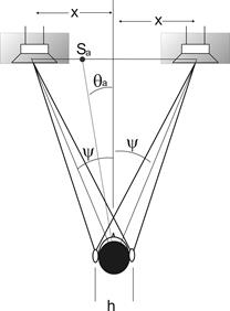
Figure 5 - Phase differences due to
inter-channel intensity ratios
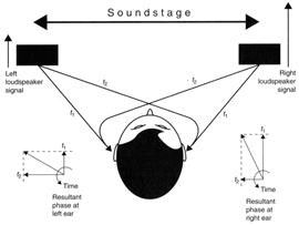
Figure 6 - How two signals which
differ only in magnitude from two loudspeakers combine at the ears to
produce signals which differ only in phase. This is the mechanism by
which stereo systems produce the illusion they do at frequencies below 1kHz
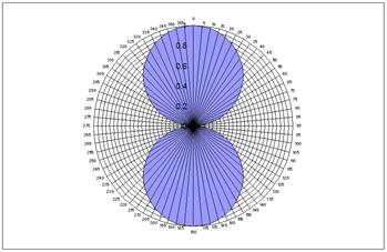
Figure 7 - The output of a
velocity microphone follows a cosine law
Encode - decode
Equations A and B may be combined together to produce
a simple expression for the reproduction of an entire encode-decode chain. It
is,
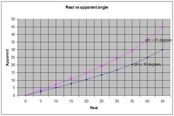
Figure 8 - θt
against θa from equation (c). See text.
HF imaging
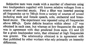
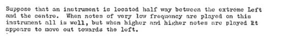
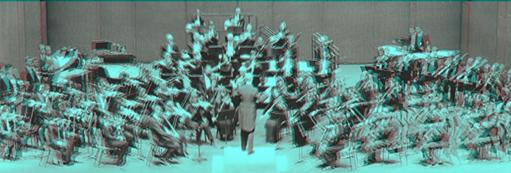
Figure 9 - A visual analogy for the
simultaneous creation of a low-frequency stereo-image and a high-frequency
stereo-image
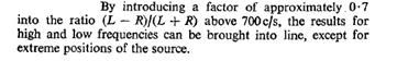
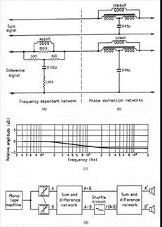
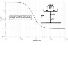
Figure 10 - EMI's Stereosonic
Shuffler and its implementation in the difference channel of a matrixed
stereo signal. Right: amplitude response of the low-pass filter in the
difference channel
Loss of the Shuffler
Delay-derived stereophony - the Precedence
effect or Law of the first wave-front
Figure 11 - Amplitude derived (left)
& delay derived (right) phantom-image positions.
Figure 12 - The failure of spaced,
omnidirectional microphones to create auditory cues similar to those
experienced in the real sound-field. Here the omnidirectional microphones and
speakers are replaced by the analogy of windows in a wall.
Wavefield synthesis (WFS) - Holographic stereophony
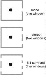
Figure 13 - If mono recordings may be
formalized as an acoustic "window" upon the original performance space, why can
we not think of stereo as two windows, and 5.1 systems as
offering 5 windows?

Figure 14 - Huygens' Principle - Each
point on a primary wave-front can be considered to be a new source of a
secondary spherical wave and that a secondary wave-front can be constructed as
the envelope of these secondary waves
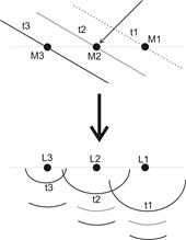
Figure 15 - In wave-field synthesis, each
electro-acoustic channel (microphone-loudspeaker) is one of Huygens' secondary
sources
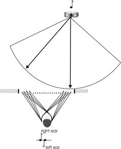
Figure 16 - The only way that
holographic stereo can be made to work is to construct a system in which the
approaching sound wave-front is sampled at many, many points - as if through a
very wide window.
Sweet spot
Stereophony in large halls
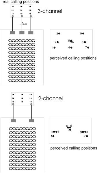
Figure 17 - Steinberg and
Snow's work on Auditory Perspective
An intermediate conclusion
Improving
stereo
Improving
Image Sharpness by means of Inter-channel Crosstalk
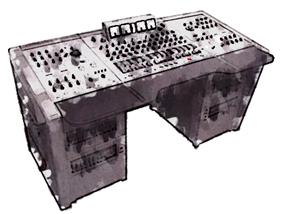
Figure 18 - EMI's iconic REDD.51 Stereosonic
console
HF
crosstalk compensation
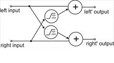
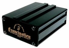
Figure 19 - The FRANCINSTIEN process
and a commercial hi-fi version of the network
Recent
developments of the FRANCINSTIEN circuit
Time doesn't stand still and experiments have
continued with the FRANCINSTIEN matrix technique. This final section therefore
reports on recent work in improvements to the crosstalk-based stereo-image
correction-filters.
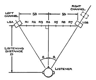
Figure 20 - Leakey's
experimental set-up.
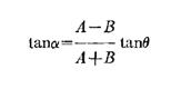
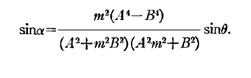
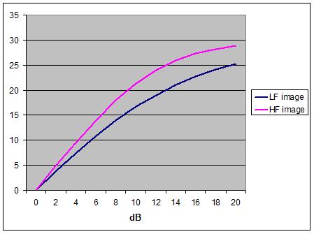
Figure 21 -HF and LF phantom image
positions vs. inter-channel intensity difference on an untreated stereo system
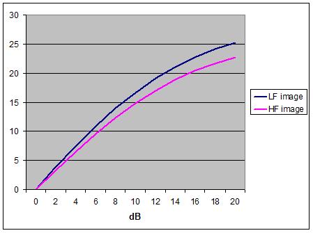
Figure 22 - HF and LF phantom image
positions vs. inter-channel intensity difference on stereo system with EMI Shuffler
(or FRANCINSTIEN) compensation
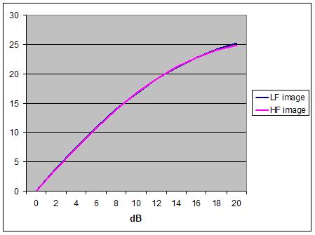
Figure 23 - HF and LF phantom image
positions vs. inter-channel intensity difference stereo system with "Bride of
FRANCINSTIEN" compensation
References
Blumlein, A. (1933) British Patent 394,325 June 14th
Clark, Dutton and Vanderlyn (1958) The Stereosonic
recording and reproducing system: a two-channel system for domestic tape
records JAES 6,2, pp102-117
REDD (1959), The EMI Stereosonic Recording Circuits:
Sum Difference, Spreader and Shuffler. EMI REDD department REF. RSL.51
Blauert, J. (1983) Spatial Hearing MIT Press
Steinberg, J.C. & Snow, W.B. Auditory Perspective
- Physical Factors. Electrical Engineering, Jan. 1934
Brice, R. (1997) Multimedia and Virtual Reality
Engineering. Newnes
Brice, R. (1998) Music Engineering. Newnes
Leakey, D.M. Measurements on the Effects of
Interchannel Intensity and Time Differences in Two Channel Sound Systems JASA
Vol 31, Number 7 July 1959.
Footnotes
[1] Note that, if
phase angles are directly proportional to frequency, as they are here, this is
equivalent to a time delay.
Links
Help Index

© Pspatial Audio 2015 - 2020. All rights reserved. ![]() Apple Certified Developer. Stereo Lab, Aria 51, Aria 20, Head Space, Groove Sleuth, iLOOP and FRANCINSTIEN T-Sym are trademarks of Pspatial Audio. FRANCINSTIEN and Bride of FRANCINSTIEN (BoF) are trademarks of Phaedrus Audio. Macintosh and the Mac logo are trademarks of Apple Computer, Inc.
Apple Certified Developer. Stereo Lab, Aria 51, Aria 20, Head Space, Groove Sleuth, iLOOP and FRANCINSTIEN T-Sym are trademarks of Pspatial Audio. FRANCINSTIEN and Bride of FRANCINSTIEN (BoF) are trademarks of Phaedrus Audio. Macintosh and the Mac logo are trademarks of Apple Computer, Inc.